Product name
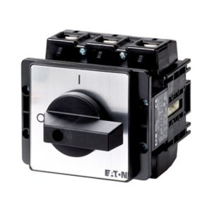
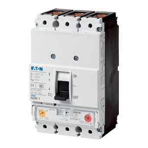
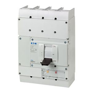
Eaton Moeller series NZM - Molded Case Circuit Breaker
Product Length/Depth
150 millimetre
Product height
105 millimetre
Product width
105 millimetre
Product weight
1.812 kilogram
Compliances
IEC
UL/CSA
RoHS conform
Certifications
CSA certified
CSA (File No. 22086)
UL listed
IEC60947
CE marking
CSA-C22.2 No. 5-09
UL (File No. E140305)
CSA (Class No. 1437-01)
UL489
UL (Category Control Number DIHS)
Product Type
Molded Case Circuit Breaker
Type
Accessory
Remote operator, can be synchronized
Number of poles
Three-pole/Four-pole
Special features
Cannot be combined with switch-disconnector PN...
Do not install M22-CK11(20/02) dual auxiliary contacts in the center auxiliary contact slot in NZM2-XRD
Used with
N(S)2(-4)
NZM2(-4)
Technical Data - Electrical
Voltage rating
24 - 30 V DC
Operating voltage - min
0.85 x Us
Operating voltage - max
1.1 x Us
Rated control supply voltage (Us) at AC, 50 Hz - min
0 V
Rated control supply voltage (Us) at AC, 50 Hz - max
0 V
Rated control supply voltage (Us) at AC, 60 Hz - min
0 V
Rated control supply voltage (Us) at AC, 60 Hz - max
0 V
Rated control supply voltage (Us) at DC - min
24 V
Rated control supply voltage (Us) at DC - max
30 V
Voltage tolerance - min
0.85
Voltage tolerance - max
1.1
Power consumption
250 W (24 - 30 V DC)
Number of operations per hour - max
120
Signal duration of remote operator at switch off - min
150 ms
Signal duration of remote operator at switch on - min
30 ms
Technical Data - Mechanical
Switch drive type
Motor drive
Special features
Cannot be combined with switch-disconnector PN...
Do not install M22-CK11(20/02) dual auxiliary contacts in the center auxiliary contact slot in NZM2-XRD
Lifespan, mechanical
20000 operations
Technical Data - Mechanical - Terminals
Terminal capacity (solid/flexible conductor)
0.75 mm² - 2.5 mm² with ferrule
18 - 14 AWG
Design verification as per IEC/EN 61439
10.2.2 Corrosion resistance
Meets the product standard's requirements.
10.2.3.1 Verification of thermal stability of enclosures
Meets the product standard's requirements.
10.2.3.2 Verification of resistance of insulating materials to normal heat
Meets the product standard's requirements.
10.2.3.3 Resist. of insul. mat. to abnormal heat/fire by internal elect. effects
Meets the product standard's requirements.
10.2.4 Resistance to ultra-violet (UV) radiation
Meets the product standard's requirements.
10.2.5 Lifting
Does not apply, since the entire switchgear needs to be evaluated.
10.2.6 Mechanical impact
Does not apply, since the entire switchgear needs to be evaluated.
10.2.7 Inscriptions
Meets the product standard's requirements.
10.3 Degree of protection of assemblies
Does not apply, since the entire switchgear needs to be evaluated.
10.4 Clearances and creepage distances
Meets the product standard's requirements.
10.5 Protection against electric shock
Does not apply, since the entire switchgear needs to be evaluated.
10.6 Incorporation of switching devices and components
Does not apply, since the entire switchgear needs to be evaluated.
10.7 Internal electrical circuits and connections
Is the panel builder's responsibility.
10.8 Connections for external conductors
Is the panel builder's responsibility.
10.9.2 Power-frequency electric strength
Is the panel builder's responsibility.
10.9.3 Impulse withstand voltage
Is the panel builder's responsibility.
10.9.4 Testing of enclosures made of insulating material
Is the panel builder's responsibility.
10.10 Temperature rise
The panel builder is responsible for the temperature rise calculation. Eaton will provide heat dissipation data for the devices.
10.11 Short-circuit rating
Is the panel builder's responsibility. The specifications for the switchgear must be observed.
10.12 Electromagnetic compatibility
Is the panel builder's responsibility. The specifications for the switchgear must be observed.
10.13 Mechanical function
The device meets the requirements, provided the information in the instruction leaflet (IL) is observed.